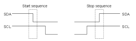
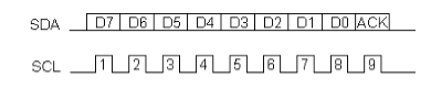
I2C Physical Protocol
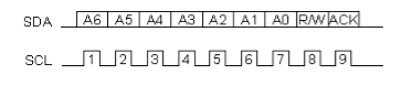
I2C Device Addressing
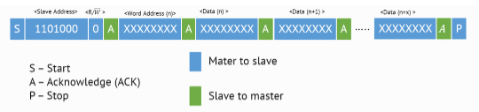
Procedure for writing time and date
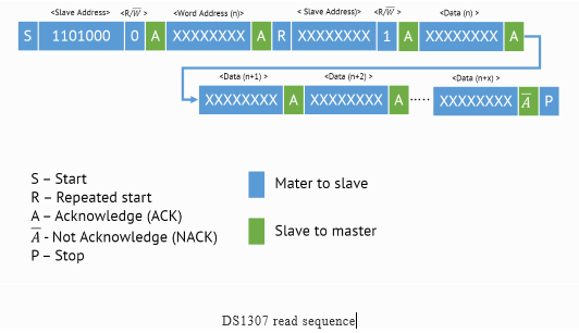
Procedure for reading the time and date
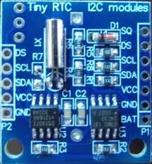
Applications
/*  Name     : main.c
 *  Purpose  : Source code for RTC Interfacing with PIC18F4550.
 *  Author   : Gemicates
 *  Date     : 2017-06-14
 *  Website  : www.gemicates.org
 *  Revision : None
 */

#include <xc.h>                      // Header file for PIC18F4550
#define _XTAL_FREQ  12000000         // 12MHZ

/****Configuration bits****/
#pragma config PLLDIV   = 5          // PLL Prescaler Selection bits(20 MHz crystal on PICDEM FS USB board)
#pragma config CPUDIV   = OSC1_PLL2  // System Clock Postscaler Selection bits
#pragma config USBDIV   = 2          // USB Clock Selection bit,Clock source from 96MHz PLL/2
#pragma config FOSC     = HSPLL_HS   // Oscillator Frequency Range
#pragma config FCMEN    = OFF        // Fail-Safe Clock Monitor Enable bit
#pragma config IESO     = OFF        // Oscillator Switchover mode disabled
#pragma config PWRT     = OFF        // PWRT enabled
#pragma config BOR      = ON         // Brown out reset
#pragma config BORV     = 3          // Brown-out Reset Voltage bits
#pragma config VREGEN   = ON         // USB Voltage Regulator
#pragma config WDT      = OFF        // Watchdog Timer Enable bit(WDT disabled)
//#pragma config WDTPS    = 32768
#pragma config MCLRE    = ON         // MCLR Pin Enable bit(MCLR pin enabled)
#pragma config LPT1OSC  = OFF        // Low-Power Timer1 Oscillator Enable bit(Timer1 configured for higher power operation)
#pragma config PBADEN   = OFF        // PORTB A/D Enable bit( pins are configured as digital I/O on Reset)
#pragma config STVREN   = ON         // Stack Full/Underflow Reset Enable bit(Stack full/underflow will cause Reset)
#pragma config LVP      = OFF        // Single-Supply ICSP disabled
#pragma config XINST    = OFF        // Extended Instruction Set

/**********LCD Pin Configuration**********/
#define LCD_DATA_PINS PORTD          // To assign LCD data pins PORTD
#define RS PORTCbits.RC1             // To assign single pin(RC1) as output
#define RW PORTCbits.RC0             // To assign single pin(RC0) as output
#define EN PORTCbits.RC2             // To assign single pin(RC2) as output
/*****************************************/

/**********Function Prototypes**********/
void LCD_Init(void);
void LCD_Cmd(unsigned char);
void LCD_Data(unsigned char value);
void LCD_Str(const unsigned char *);
void USART_Init(void);
void USART_Write(unsigned char);
void USART_Write_Str(const unsigned char *);
void USART_Write_Str_Line(const unsigned char *);
void USART_Write_Int(int ,unsigned char);
unsigned char USARTReadByte();
void I2C_Init(void);
void I2C_Start(void);
void I2C_Restart(void);
void I2C_Stop(void);
void I2C_Wait(void);
void I2C_Send(unsigned char dat);
unsigned char I2C_Read(void);
unsigned char rtc1307_read(unsigned char address);
unsigned char BCD2UpperCh(unsigned char bcd);
unsigned char BCD2LowerCh(unsigned char bcd);
/************************************/

unsigned char sec,min,hour,date,month,year;
const unsigned char time[] = "TIME:";
const unsigned char date_format[] = "DATE:";
const unsigned char rtc[] = "RTC DS1307";

void main()
{
	TRISC = 0x80;	                      //Reception Pin as Input Pin, rest all as output Pin
	TRISD = 0x00;	                      //PORTD as output
	LCD_Init();                           //Initialize LCD Module
	USART_Init();	                      //Initialize USART at 9600 BPS
	LCD_Cmd(0x84);                        //first line fourth character
	LCD_Str(rtc);                         //display rtc
	__delay_ms(10);
	I2C_Init();	                      //Initialize I2C
	__delay_ms(10);
	I2C_Start();                          //Start the I2C protocol
	I2C_Send(0xD0);                       //7-bit DS1307 address
	I2C_Send(0x00);
	I2C_Send(0x80);	                      //CH = 1 Stop oscillator
	I2C_Send(0x00);	                      //Minute
	I2C_Send(0x06);                       //Hour
	I2C_Send(0x02);	                      //Sunday
	I2C_Send(0x28);	                      // 28 APRIL
	I2C_Send(0x04);                       //  4 April
	I2C_Send(0x95);	                      // 1995
	I2C_Stop();                           //Stop the I2C Protocol
	__delay_ms(10);

	I2C_Start();                          //Have to start the Clock again
	I2C_Send(0xD0);                       //7-bit DS1307 address
	I2C_Send(0x00);                       //7 bit address start
	I2C_Send(0x00);	                      //start Clock and set the second hand to Zero
	I2C_Stop();
	__delay_ms(10);
	LCD_Cmd(0x01);                        //Clear display screen

	while(1)                              //Infinite Loop For Reading Time and Date
	{
		sec = rtc1307_read(0x00);     //Seconds address

		min = rtc1307_read(0x01);     //min address

		hour = rtc1307_read(0x02);    //hour address

		date = rtc1307_read(0x04);    //date address

		month = rtc1307_read(0x05);   //month address

		year = rtc1307_read(0x06);    //year address

		__delay_ms(1);                //delay of 1ms
		LCD_Cmd(0x80);                //Cursor to beginning of 1st row
		LCD_Str(time);                //To display the time
		LCD_Data(BCD2UpperCh(hour));  //BCD format to Upper Clock halt bit(hour)
		LCD_Data(BCD2LowerCh(hour));  //BCD format to Lower Clock halt bit(hour)
		LCD_Data(':');                //To display ':'
		LCD_Data(BCD2UpperCh(min));   //BCD format to Upper Clock halt bit(min)
		LCD_Data(BCD2LowerCh(min));   //BCD format to Lower Clock halt bit(min)
		LCD_Data(':');                //To display ':'
		LCD_Data(BCD2UpperCh(sec));   //BCD format to Upper Clock halt bit(sec)
		LCD_Data(BCD2LowerCh(sec));   //BCD format to Lower Clock halt bit(sec)
		LCD_Cmd(0xC0);                //Cursor to beginning of 2nd row
		LCD_Str(date_format);         //To display the date
		LCD_Data(BCD2UpperCh(date));  //BCD format to Upper Clock halt bit(date)
		LCD_Data(BCD2LowerCh(date));  //BCD format to Lower Clock halt bit(date)
		LCD_Data('/');                //To display '/'
		LCD_Data(BCD2UpperCh(month)); //BCD format to Upper Clock halt bit(month)
		LCD_Data(BCD2LowerCh(month)); //BCD format to Lower Clock halt bit(month)
		LCD_Data('/');                //To display '/'
		LCD_Data(BCD2UpperCh(year));  //BCD format to Upper Clock halt bit(year)
		LCD_Data(BCD2LowerCh(year));  //BCD format to Lower Clock halt bit(year)
		__delay_ms(10);               //delay of 10ms
	}
}

/**********************************************/

/****************RTC FUNCTIONS*****************/
unsigned char BCD2UpperCh(unsigned char bcd)
{
	unsigned char temp;
 	temp = bcd >> 4;
 	temp = temp | 0x30;                   //Lower 3-bits
 	return(temp);
}
unsigned char BCD2LowerCh(unsigned char bcd)
{
	unsigned char temp;
 	temp = bcd & 0x0F;                    //Making the Upper 4-bits
 	temp = temp | 0x30;
 	return(temp);
}

unsigned char rtc1307_read(unsigned char address)
{
	unsigned char temp;
	I2C_Start();
	I2C_Send(0xD0);
	I2C_Send(address);                    //I2C function
	I2C_Restart();
	I2C_Send(0xD1);
	temp = I2C_Read();
	I2C_Stop();
	return temp;
}
/**********************************************/

/*****************LCD FUNCTIONS****************/
void LCD_Init()
{
	EN = 0;                              //Enable function
	__delay_ms(1);                       //delay of 1ms
	LCD_Cmd(0x38);                       //function set:8 bit,2nd line,5x7 dots
	__delay_ms(1);                       //delay of 1ms
	LCD_Cmd(0x0E);                       //Display On,Cursor On
	__delay_ms(1);                       //delay of 1ms
	LCD_Cmd(0x0C);	                     //Display On Cursor Off
	__delay_ms(1);                       //delay of 1ms
	LCD_Cmd(0x01);                       //Clear display screen
	__delay_ms(1);                       //delay of 1ms
	LCD_Cmd(0x06);                       //Entry mode
	__delay_ms(1);                       //delay of 1ms
	LCD_Cmd(0x80);	                     //Cursor to beginning of 1st row
	__delay_ms(1);                       //delay of 1ms
}

void LCD_Cmd(unsigned char value)            //LCD command function
{
	LCD_DATA_PINS = value;               //LCD data pins PORTD
	RS = 0;                              //Register select(command mode)
	RW = 0;                              //Read/Writ(Write operation)
	EN = 1;                              //Enable pin
	__delay_ms(1);                       //delay of 1ms
	EN = 0;	                             //Disable pin
}
void LCD_Data(unsigned char value)           //LCD data function
{
	LCD_DATA_PINS = value;               //LCD data pins PORTD
	RS = 1;                              //Register select(Data mode)
	RW = 0;                              //Read/Write(Write operation)
	EN = 1;                              //Enable pin
	__delay_ms(1);                       //delay of 1ms
	EN = 0;	                             //Disable pin
}

void LCD_Str(const unsigned char *str)       //LCD string
{
	while((*str)!='\0')
	{
		LCD_Data(*(str));

		str++;                       //Increment the Pointer
	}
}


void USART_Init(void)                        // Serial Port UART
{

	SPBRG = 77;                          //Baud Rate = 9600 Bits per Second


	TXSTAbits.TXEN=1;                    //Enable Transmission by setting these Value's
	TXSTAbits.BRGH=0;                    //BAUDRATE is low


	RCSTAbits.SPEN=1;                    //Enable Reception by Setting these Value's
	RCSTAbits.CREN=1;	             //Enable Receiver (RX)

	//BAUDCON
	BAUDCONbits.BRG16=0;

}

void USART_Write(unsigned char value)
{

	while(PIR1bits.TXIF == 0);           //Wait for TXREG Buffer to become available
	TXREG = value;                       //Transmitter register
}

void USART_Write_Str(const unsigned char *str)
{
	while((*str)!='\0')
	{

		while(PIR1bits.TXIF == 0);   //Wait for TXREG Buffer to become available

		TXREG = *(str);              //Write Data


		str++;                       //Increment the Pointer
	}
}


void USART_Write_Str_Line(const unsigned char *str)
{
	USART_Write_Str(str);
	//USART_Write_Str("\r\n");
	//Formely I used to write this
	USART_Write(10);
	USART_Write(13);

}


void USART_Write_Int(int val,unsigned char field_length)
{
	char str[5]={0,0,0,0,0};
	int i=4,j=0;
	if(val<0)
	{
		USART_Write('-');	     //Write '-' sign for negative numbers.
		val=(val*(-1));		     //Make it positive.
	}


	while(val)                           //Convert Number To String and pump over Tx Channel.
	{
		str[i]=val%10;
		val=val/10;
		i--;
	}
	if(field_length>5)
		while(str[j]==0) j++;
	else
		j=5-field_length;

	for(i=j;i<5;i++)
	{
		USART_Write('0'+str[i]);
	}
}
unsigned char USARTReadByte()
{
	while(!PIR1bits.RCIF);	             // EUSART Receive Interrupt Flag bit(Wait for a byte)

	return RCREG;                        //EUSART Receive Register
}

void I2C_Init()
{
	TRISB |= 0x03;                       //PORTB as SDA and SCL enable pin
	SSPSTAT |= 0x80;                     // MSSP STATUS REGISTER (SPI MODE) Slew Rate Disabled
	SSPADD = 119;                        //MSSP Address Register (SSPADD)

	SSPCON1 = 0b00101000;		     //Master mode
	SSPADD = 119;                        //MSSP Address Register (SSPADD)
	/*SSPEN = 1
	Enables the Serial Port and configures the SDA and SCL
	Pins as the Serial Pins
	SSPM3:SSPM0 --> 1000
	I2C Master Mode
	Clock = Fosc/4*(SSPADD+1)
	*/
}

void I2C_Start(void)
{
	SSPCON2bits.SEN = 1;                 //Start Condition Enable/Stretch Enable bit
	//SSPCON2 bit 0
	while (SSPCON2bits.SEN == 1)         //SEN =1 initiate the Start Condition on SDA and SCL Pins
		continue;


}

void I2C_Restart(void)
{
	SSPCON2bits.RSEN = 1;                //SSPCON2 bit 1

	while (SSPCON2bits.RSEN == 1)        //RSEN = 1 initiate the Restart Condition
		continue;                    //Automatically Cleared by Hardware


}

void I2C_Stop(void)
{
	SSPCON2bits.PEN=1;                   // Initiate Stop condition on SDA and SCL pins.

	while(SSPCON2bits.PEN==1)            //Automatically cleared by hardware.
		continue;
}

void I2C_Wait(void)
{
	while(SSPSTATbits.R_NOT_W == 1)
		continue;
	if(SSPCON2bits.ACKSTAT == 1)         //If ACKSTAT bit is 0 Acknowledgment Received Successfully
	{
		I2C_Stop();
	}

	//Otherwise Not
}

void I2C_Send(unsigned char dat)
{
	SSPBUF = dat;                       // Move data to SSPBUF */
    while(SSPSTATbits.BF);                  // wait till complete data is sent from buffer */
    I2C_Wait();                             // wait for any pending transfer */
}

unsigned char I2C_Read(void)
{
	unsigned char temp;
    SSPCON2bits.RCEN = 1;                  // Enable data reception
    while(SSPSTATbits.BF == 0)             // wait for buffer full
    	continue;
    temp = SSPBUF;                         // Read serial buffer and store in temp register
    I2C_Wait();                            // wait to check any pending transfer
    SSPCON2bits.ACKDT=1;	           //send not acknowledge
	SSPCON2bits.ACKEN=1;
	while(SSPCON2bits.ACKEN == 1)
		continue;
	                                   //I2C_Stop();
    return temp;                           //return the read data from bus */
}